Power Relay Control
Because thermal control is an issue for APOLLO, we can't afford to leave our electronics on most of the time. About 30 minutes before operation, the night assistant will walk to the base of the 3.5-m pier and turn a key (or some such action). This will have the effect of sending a logic level high, which will activate relays to turn on the laser, the two chillers, the timing electronics, APDs, and other APOLLO equipment that needs time to warm up and establish a thermally stable state.
In addition to this, we will sometimes want to perform system tests (calibrations, etc.) without the benefit of the laser and chillers. For instance, we would like to be able to power the CAMAC crate, APDs, CCD camera, etc. at our disgression (provided we have approval of the observatory). We would also like to be able to control thermal devices: auxillary pumps, fans, heaters, etc. in an automated way.
So we want to have the 8 available digital outputs activate various devices in a smart way. We additionally need to combine the logic of the master switch in some cases (in an OR configuration). So we want banks of relays switched by a TTL logic signal that has been generated/combined near the computer. Below is a list of possible devices associated with the 8 logic outputs. Bold entries are also powered by the master switch. The location of the power supply for each is indicated as laser (L), cabinet (CAB), and intermediate-level platform (IL).
So I count 4 items in the laser enclosure, 4 in the intermediate-level enclosure, and at least six in the cabinet. The "other ranging electronics" entry represents sundry un-thought-of items that will have power supplies (or exist wholly) in the cabinet and are needed for ranging (e.g., the interlock system), so these could be several in number.
So some of the spaces will need more than four outlets, but many of these may be rigged in parallel, so that we can probably get away with 12 control lines. But let's make it 16 for good measure. As the list appears above, eight control lines would do, but let's allow the freedom to have the same digital channel out of the computer control things in different locations (thereby needing multiple lines out). Probably four control lines to the intermediate level and six to the cabinet and six to the laser enclosure would satisfy all our needs.
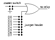
A scheme for accomplishing this would be to make 16 2×8 headers for jumpers, each rigged as shown below. This is repeated 16 times, so that each of the 8 digital outputs has a chance to control any of the relays. The master switch is also jumper-configurable to either work or not for that output.

Using this scheme, item three on the list above can have some units powered by the master switch and some not, even though they are on the same digital line as far as the computer is concerned. The T/R motor puts out a fair bit of heat, so there is no need to turn it on until ranging is about to actually start.
As for relay power requirements, the beefiest item on the list is the IL enclosure exhaust fan, which has a start-up current of 3.5 amps or so, but a steady-state current of 1.5 amps. The rest of the devices are at largest one amp (CAMAC crate and laser enclosure heater).