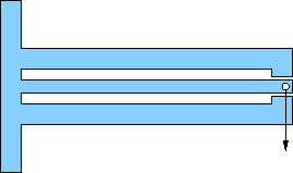
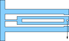
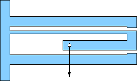
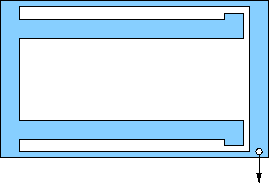
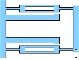
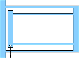
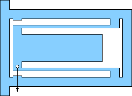
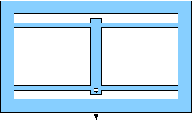
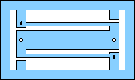
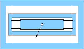
Pick one of the flexures below for your design. All are based on an outer rectangular envelope of 17×11 centimeters, except for a few (e, f, g) that have tabs on the left extending a centimeter or so up and down (for clamping). Most others can be clamped without the tabs.
All show a location (hole) for the application of force. It is usually obvious which pieces are meant to flex (thin). The structural members are about 1 cm wide, which should be plenty strong compared to the flexures (remember strength goes like cube of bending thickness). This will often translate to a flexure beam length of about 15 cm.
All have motion-limits built-in so-as not to exceed the design displacements. Pay attention to these and tune gaps according to the design capability. Sometimes the structure comes from the rectangular wall.
Assume all parts to be made from 0.25-inch-thick (6.35 mm) lucite (a.k.a. acrylic or plexiglass). The modulus of elasticity is 3.0×10⁹ Pa, and the yield stress is 107 Pa.
The drawings below have no fillets for strain relief. These may or may not be necessary for your part. Use SimulationXpress to tell you if you are exceeding yield stress limits at the corners to decide.
You can also create your own flexure geometry provided you get approval from the professor/TA.
 |
a) Simple cantilever beam, end-loaded, uniform thickness. Design for max displacement 3.0 mm at end. |
 |
b) Cantilever flexure. Design beam length (flexible part) for 30 mm. The thicker part of the moving structure has a hole cut out for light-weighting, but will be very strong despite thin upper and lower walls. Design for 3.0 mm displacement at end (must calculate angle that flex beam must bend). |
 |
c) S-bend flexure. By loading the beam midway along its length, a moment is transferred to the end that results in zero end-slope. In other words, the 90-degree angle-piece attached to the end of the beam will simply translate without rotation. Design for an end displacement of 3.0 mm. |
 |
d) Dual-beam translation stage. The geometry ensures that the end-piece does not rotate as the piece flexes, though there will be a tiny bit of translation toward the clamped end, since bending flexures must shorten their projected length if they do not also stretch while bending (which these will not). Design for a max displacement of 3.0 mm. |
 |
e) Dual flexure translation stage. Similar to above, but using two flexing bits at each end of the flexure beams. The flexure beams have a light-weighting hole, but are quite strong even if the side-walls are thin. Design with a beam (flexing part) length of 30 mm, and aim for a maximum deflection of 3.0 mm. |
 |
f) Dual-stage translation. An improvement on d) above, because as both pairs of legs shorten in projection, the effect mostly cancels for the stage where the load is attached. Design for 4.0 mm total displacement: 2.0 mm for each stage. Note tricky detail: the bending thicknesses of the two sets of flexures will be different. Adjust them so that the force required is the same when each stage deflects by 2.0 mm. In other words, you're only applying one force, and this will apply to both stages. You want the deflection of each stage to be equal under this force or the clever cancellation trick will not work as perfectly. The SimulationXpress displacement coloration of the right-hand end should wind up halfway along the color scale (green) if done correctly. |
 |
g) Alternate topology for translation stage. This one may pick up some rotation, too. So should you assume the beams flex into an arc, or an S-shape as in c), d), and f)? Design for 2.0 mm max deflection. |
 |
h) Two-sided translation stage. This will experience no sideways deflection (the problem d) had) due to symmetry. The force required may be more than initially calculated because flex beams will be forced to stretch some. Design for displacement of 1.0 mm. |
 |
i) Torsion stage. This allows the platform to rotate, by flexing the beams into arcs. Design for 2.0 mm of deflection at the ends of the platform (for angle of 4 mm over the length of the platform). Besides assessing the force necessary for the torsion, how much force would be required to translate the stage by 2.0 mm? Is it easier to rotate, or translate? |
 |
j) A 2-d translation stage. The platform in the middle should respond to a force in any direction, allowing 2 degrees of freedom. For the flex members, we'll assume the use of plastic rulers with a modulus of 3.6×10⁹ Pa, and a yield stress of 4×10⁷ Pa (more forgiving than the lucite). The ruler is 0.025 inch thick, or 0.635 mm. Make the flex members 20 mm long. For the SimulationXpress analysis, make a single structure all out of the same material. If we were to make this, we'd put slots in the lucite just thick enough for the ruler pieces and epoxy ruler pieces in place to assemble. Design for a displacement of 1.0 mm in both directions. |