Due Tue., Jan. 19 or Wed., Jan. 20 depending on section
In this lab, we will explore the use of various motors, which forms the basis for any motion control that a project might incorporate.
We will explore three common motor types, and learn how to control their motion. First will be servo motors, including both messing with the ATMega PWM frequency settings, as well as use of the Servo library for Arduino. Next, we'll take up use of the motor shield, so that we can more easily drive stepper motors, and lastly DC motors.
Note that generally speaking, motors take a fair bit of power/current, so the Arduino—limited to 40 mA per pin—will not be able to directly drive the steppers or DC motors. We could incorporate an H-bridge transistor arrangement to handle the drive current, and that's essentially what the motor shield does for us.
Let's pretend we don't have access to a fancy library for servo motors, and we want to directly drive a servo motor with an appropriately timed PWM pattern. Looking at the HiTec "manual", we find that we want to send a PWM output at 50 Hz, with a low duty cycle: 0.9 ms (out of 20) to 2.1 ms sends the servo through its full (approx. 180°) range. This corresponds to 4.5% (11/255) to 10.5% (27/255) duty cycle.
But the PWM frequency if you do a straightforward AnalogWrite() is not at all 50 Hz, and the motor will not respond. So we have to change the frequency. Even then, we have limited choices available. On the Uno/Nano, the 6 available PWM pins are run off of three different internal timers, each of which have their own "prescaling" options for variable output speed, according to the following table (defaults bold):
| PWM pins | Register | prescaler values | frequencies (Hz) |
| 5, 6 | TCCR0B | 1, 2, 3, 4, 5 | 62500, 7812, 977, 244, 61.0 |
| 9, 10 | TCCR1B | 1, 2, 3, 4, 5 | 31250, 3906, 488, 122, 30.5 |
| 3, 11 | TCCR2B | 1, 2, 3, 4, 5, 6, 7 | 31250, 3906, 977, 488, 244, 122, 30.5 |
Our closest option to 50 Hz involves the use of timer 0 (pins 5 or 6) with divider option 5 (61 Hz). This means we can cover the required 0.9 to 2.1 ms pulses with duty cycles ranging from 14/255 to 33/255, leaving only 20 possible steps by this scheme. But let's go for it!
TCCR0B = TCCR0B & 0b11111000 | 0x05;
to replace the last three bits of the TCCR0B register with 101. See the short or full version of the ATMega328 datasheet for background info. Write out analog values to pin 5 or 6 corresponding to the range of duty cycles sought by the servo, and send this into the scope to look at the waveform. Use the measurement menu to measure the frequency of the waveform, and make a table of the pulse width (also via automatic scope measurement) as a function of the analogWrite() parameter. No need to step through every possibility, but empirically find the value that delivers the closest to 0.9 ms and 2.1 ms, and perhaps one or two values in the middle. Also, while you're messing around, change the last three bits in the TCCR0B register to something other than 5 so you can verify control over the frequency as per the table above.
Having ironed out a range of settings to approximate the specified parameters of the servo, let's make a program for interactive control. You will type a single-digit number from 0 to 9 into the serial monitor, and the servo will move to the appropriate position.
The Arduino has enough juice to drive the servo, which has three leads. Black is ground, red is +5 V, and the other color (yellow, often) is the PWM control lead. Use Serial.available() and Serial.read() to check for serial input and read a single character (type char) if necessary. Since C stores a char as an 8-bit entity in memory (according to the ASCII table), it can be subtracted very easily from integers, or other characters. In particular, subtracting '0' from a character will result in the integer offset of that character from zero. A further convenience is the
map(value, input_min, input_max, output_min, output_max)
function, which can take a value between zero and nine, for instance, and map it onto a different range. An example loop to get the job done is:
void loop()
{
  if (Serial.available()){                  // check if incoming serial data
    ch = Serial.read();                     // read single character
    if (ch >='0' && ch <='9'){              // use 10 step range for demo
      level = map(ch-'0',0,9,XX,YY);        // map 0-9 onto XX-YY
      analogWrite(SERVO, level);            // send to servo
      Serial.print("Setting servo level to: ");
      Serial.println(level);
    }
  }
  delay(50);                                // interactive program, so slow
}
Don't copy and paste, but read, comprehend, adapt. You should now be able to run your servo in this interactive way. Have a TA/prof check your functionality.
Turn in your interactive servo control code, along with your scope measurements of PWM frequencies (more than just the ~61 Hz setting) and your table of digital values and associated pulsewidth. Also, although in this case it may seem painfully simple, make a block diagram of your hookup/setup, indicating which pins do what and how the motor is connected.
Servos are capable of fine angular control, so it is a shame to use our PWM frequency kludge to only get twenty or so steps. The ATMega chip is certainly capable of better control. After all, it runs at 16 MHz, and therefore has 60 ns clock steps. In principle, the 1.2 ms range of pulse widths should be divisible into 20,000 units, not 20. Now, the servo itself is not likely dependable at this level, but the point is that the ATMega should be.
So folks have worked out a Servo library to exercise better control of a servo, and made it part of the standard Arduino distribution. To use it, simply include the library and instantiate a servo motor in the preamble of your code/sketch:
#include <Servo.h>				// Servo library

Servo hitec;					// hitec is handle for Servo instance
Note that hitec is just an arbitrary name to give your motor. It's essentially a variable, or handle, with type Servo. Call it whatever you want. You could also instantiate more than one with a line like: Servo serv1, serv2;, if desired. In the setup(), you need to attach the servo handle to a specific pin. This could be as simple as:
hitec.attach(9)
to attach to pin 9. Or, if you want to tune the servo so that 0° and 180° really mean what they say, you can specify a minimum pulse time, in microseconds, and a maximum pulse time as well:
hitec.attach(pin, minpulse (μs), maxpulse (μs))
The default minimum and maximum is 544 μs and 2400 μs. Taking the Hitec "manual" literally, one would expect values of 900 and 2100. From the Arduino Reference page:
Feel free to increase these endpoints until the servo no longer continues to increase its range. Note however that attempting to drive a servo past its endpoints (often indicated by a growling sound) is a high-current state, and should be avoided.
Note that timer1 is used for the servo control, so on the Uno/Nano, this disrupts normal use of the PWM functionality on these two pins. Otherwise, the servo can be attached to pins 2–13, even non-PWM pins!
To move the servo, simply say hitec.write(deg), where deg is between 0 and 180. Or you can have finer, lower level control with hitec.writeMicroseconds(), where the argument is the desired pulsewidth, in microseconds. You may want to put in protective clauses in your code to prevent accidental driving of the servo beyond its intended range.
Okay, now that you are familiar with the ingredients, write a simple program to tune up your servo's minimum and maximum pulsewidths corresponding to 0° and 180°. Start by using 900 and 2100 in the attach() command, and perhaps sending the motor to 0°, 90°, and 180° delaying a couple seconds between moves for you to assess the quality of alignment. Iterate values of the min and max pulsewidths until you have it down. You may optionally look at the pulses on the scope to see if the output really is nailing the pulsewidths you are requesting. Could be interesting. Keep this tuning program around, as you may want to use it later in your project to tune a servo you pick up to use at that time.
Having calibrated your servo, now do something semi-creative in controlling it. Whether it is an interactive "move where I tell you" program, or execution of an interesting pattern of motion, or some other idea—it's up to you. If stepping through some pattern, don't forget to put delays in, and perhaps go in small increments towards your goal, with short delays between steps.
Include your final servo control code, whose functionality was checked by a TA/prof. Include (in code/comments) the tuning you used for your servo. Also make sure the comments explain what the program/motion is meant to accomplish. Include a block diagram if how the system is hooked up, to further develop the habit of diagramming your setup (will become much more important in project phase).
Note: This section may take the longest; feel free to skip to Exercise 4 if time is short.
In this exercise, you will use the motor shield to drive a stepper motor. The motor shield (schematic here) provides support for two servo motors (driven from pins 9 and 10 on the Uno), and either 2 stepper motors, 1 stepper and 2 DC motors, or 4 DC motors.
It is generally advantageous to supply external power to the motor shield. To do this:
First, you will need to get the driver for the shield. This is not part of the standard Arduino Library, so as a result you will get experience obtaining third-party libraries and installing them in your local space.
You can find documentation on how to use the motor shield at the motor shield site. There, you can find a set of instructions for installing the library. I repeat the instructions here for convenience:
If you want, run the MotorParty example. Or keep it in mind for future exploration.
The key steps needed to get a stepper motor running are:
NSTEPS is straightforward, as is FORWARD vs. BACKWARD (though these are somewhat arbitrary, depending on your coil polarity/hookup). The type of step deserves some elaboration, though.
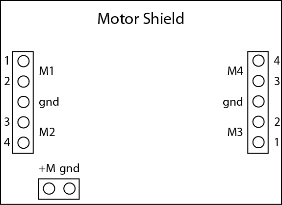
SINGLE turns on one coil at a time, grounding one side and putting the other at the supply voltage. Each step therefore jerks the motor to a slightly different position. The sequence of activated pins on the terminal strip (numbering 1–4 downward on left, ignoring ground; see this diagram for clarification) is 3, 2, 4, 1, repeating.
DOUBLE has two coils on at once, and therefore consumes twice the current, providing twice the torque. The rotor position will be halfway between the steps seen in the SINGLE scheme. Coils are turned on as follows: 1/3, 3/2, 2/4, 4/1. In the second step, when leads 2 and 3 are energized, the rotor will be between the first and second positions in the single sequence above. And so it continues along the sequence. Note that the steps are the same size as in SINGLE mode.
INTERLEAVE performs a half-step sequence, merging the two sequences above. It therefore takes twice as many steps to complete a revolution. One has finer control, and the power will be between that of SINGLE and DOUBLE modes, in general. But if you park on a double-coil position for a while, you're at twice the power than if you happen to park on a single coil position. The sequence is: 1/3, 3, 3/2, 2, 2/4, 4, 4/1, 1, and repeats. You can see that the rotor is more gently walked along the sequence in smaller nudges.
We will leave off detailed discussion of Microstepping for now. Suffice it to say that transitions from one step to the next are handled by PWM ramping of the signal levels to make a smooth handoff to the next step.
Now you have the nuts and bolts defined for you, you're ready to do something with the motor.
The first thing you should try is moving the motor by the number of steps (SINGLE type) that you suspect makes a full revolution. Put a mark or tape or cardboard or something on the shaft to let you see the revolutions, and see if you can get it precisely back to the same place. Put a delay in the loop long enough to judge position, and perhaps alternate back and forth until you are in the right ballpark. When it looks pretty good, you can chop out the reverse section and see if repeated forward moves accumulate error. You should know after a few revolutions. But if you run for several minutes you'll develop an appreciation for what a stepper delivers: confident positioning time after time, never losing a step.
Now you can do one of several things for you stepper "demonstration." The point is to get you to use the stepper in some way that is informative to you, and potentially useful down the road. You can deviate from the following suggestions, but just make sure your task is not too trivial to count. Run the idea by a TA/prof for approval. Some possible tasks include:
Have a TA/prof check the behavior of your creation, and print out the program for submission. Indicate what kind of motor you used and how many steps you found it to have. Make a block diagram of your stepper configuration.
The motor shield can use most of the Uno's pins. It is not easy to find info on which pins are unavailable when the motor shield is in use. Here is an excerpt (several corrections from original!) detailing the pin usage:
All 6 analog input pins are available. They can also be used as digital pins (pins #14 thru 19)
Digital pin 2, and 13 are not used.
The following pins are in use only if the DC/Stepper noted is in use:
Digital pin 11: DC Motor #1/Stepper #1 (activation/speed control)
Digital pin 3: DC Motor #2/Stepper #1 (activation/speed control)
Digital pin 6: DC Motor #3/Stepper #2 (activation/speed control)
Digital pin 5: DC Motor #4/Stepper #2 (activation/speed control)The following pins are in use if any DC/steppers are used
Digital pin 4, 7, 8 and 12 are used to drive the DC/Stepper motors via the 74HC595 serial-to-parallel latchThe following pins are used only if that particular servo is in use:
Digital pin 10: Servo #1 control
Digital pin 9: Servo #2 control
Almost there. The last type of motor we will look at is a DC motor. These are very simple, but can easily exceed the capabilities of the shield. The H-bridge use on the shield can only handle loads up to 0.6 A. This may sound like a lot, but you'd be surprised, when it comes to motors.
Now that you've seen the stepper example using the motor shield and associated library, it will be very easy to run a DC motor. Here's what you need to do:
DC motors are not truly controllable in terms of speed, as this depends on the load the motor sees. But the PWM control exerted by setSpeed() at least provides variable speed capability at a given load. Note that at the lower end of the range, motors may decide to simply stall.
So what do you need to do? Pretty simple for this one. Make a program that ramps up a motor's speed over something like five seconds, than ramps it back down again, in a repeating pattern. Try to hit the max speed and something close to a minimum speed that reliably does not stall (so give a little margin on the low end). Turn in the code that made your oscillating speed motor and have a TA/prof check the functionality of the code. Also include a block diagram.
Back to Phys 124 Lab Information Page