Due Tue., Feb. 9 or Wed., Feb. 10 depending on section
This week, we will put together a mini-project that has the right flavor for the ultimate project, albeit a little on the simple side (being feasible in one week).
Rather than making step-by-step instructions, as has been typical of the first three labs, this one will be presented as a project proposal. Then it serves two purposes:
It is often desirable to track a source of light. A common application would be aligning a solar panel to the brightest part of the sky (usually the sun, but could be the brightest area in clouds). Or a missile defense system may want to follow the hot, bright plume of a rocket. Sea turtles hatching out of the sand at night follow the brightest direction to get them to the sea. Just sayin'.
So we will design and build a sensor assembly that can tell the directionality of light, and actuate a servo motor in response to point the sensor assembly toward the light. For simplicity, we will confine the motion of our device to a one-dimensional arc. In order to avoid noisy, power-consuming dithering, we will allow a dead space where the system is "happy" to stay put. If the "platform" is moved too far, such that it risks colliding with the ground (for instance), a light sensor will trigger an interrupt and take corrective action. Finally, when the light level gets too low, the platform will return to the "straight up," or centered position and await sufficient light to resume operation.
Our device is intended to track a light source by sensing and quantifying different light levels from two detectors pointed in slightly different directions.
We don't want the device to keep hunting through the night, so we will set a minimum light level at which to operate, returning to 90° (straight up) to await sunrise.
We don't want a fussy dithering (oscillatory) action once the best position is found, so we will ignore differences that are too small.
Because the absolute light level may vary, we do not want to make decisions on moves based on an absolute difference, but rather something that scales with the average value of the two readings: more like a ratio. Again, we will cease to operate once the light level becomes too low.
The size of the move will be proportional to the difference in light intensity, so that it will quickly chase an obvious, large light difference. But motion will drop to smaller moves as the difference gets smaller. We will probably limit the largest move to 5 or 10° so that our device is not too erratic in its zeal to satisfy the sensors.
We will not let the servo exceed the 0–180° range.
When the proximity sensor detects a fault, the system will back off a little bit, and reset the maximum allowable angle to be just shy of the limit. We may also consider making the limiting angle expire after some time in case the obstruction changes, so the blocked territory is not forever out of bounds. We will implement the expiration date on the limit if time allows.
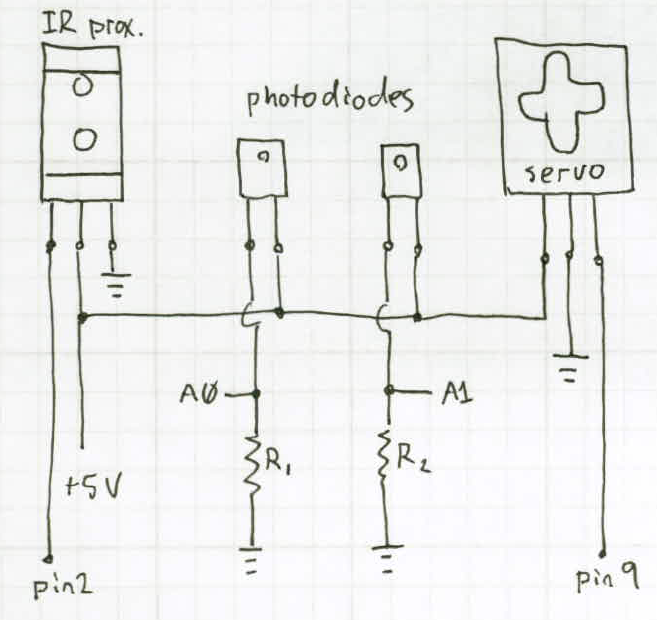
We will use QSE-133 phototransistors for light sensing. Each will be tilted something like 20° to 30° to the left and right of the platform normal, so-as to sense a 2-point gradient of which way is brighter. Each will be supplied with 0 and +5 V, and put in series with a resistor (on the ground side) in the 1–10 kΩ range, depending on the light level being sensed. The voltage across the sensing resistor increases with light level, and will be read as an analog input.
We will use an infrared Sharp GP2Y0D805Z0F digital distance sensor to determine when our platform is in danger of collision. This device is to be supplied with 0 and +5 V, and the digital output will be hooked to an interrupt-capable digital input of the Arduino Uno. The device normally sits in the high state, but drops low when an object gets too close.
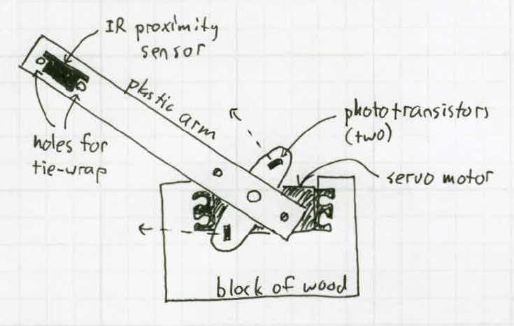
The servo motors are packaged with a variety of plastic attachment pieces. We will use the plus-shaped red piece. The photosensors will be placed on opposite arms, facing "up" at the midpoint (90°) position. On the cross arm, we will mount a long strip of plastic to hold the collision sensor at the end, to give it positional leverage (see diagram below).
The red plus fitting has small holes along the centerline which can accommodate the legs of the phototransistors. We have found that the legs themselves can secure the phototransistor adequately by placing the device in the middle two holes and bending the legs back around through the first and fourth holes. In order to have the sensors facing slightly different angles (for sensing the gradient), we can just give them a gentle but firm twist once mounted by their legs.
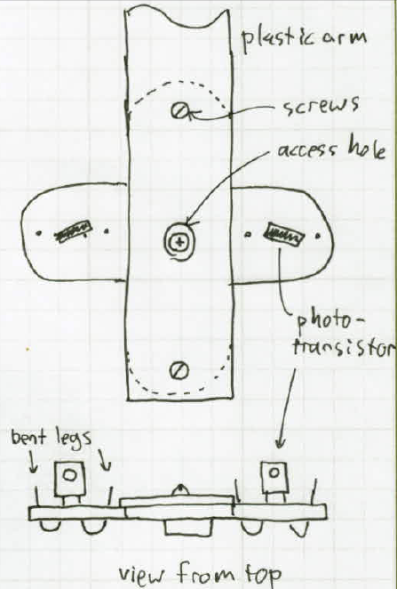
The plastic strip holding the distance sensor can be screwed into the holes in the plus-piece with #2-56 screws, providing that we first enlarge the holes slightly with a #49 drill. A larger hole in the strip allows access to the central screw that hols the red-plus onto the servo.
Mounting the distance sensor is slightly tricky: we will have to tie-wrap the device on its side at the end of the plastic strip, through holes drilled in the strip.
We will mount the servo on a block of wood from the scrap drawer in the workroom.
The phototransistors need a sensing resistor, +5 V, and ground. The distance sensor needs +5 V and ground, plus one signal connection. Since the parts are in motion, we will minimize the number of cables going to the platform. We will also put the sensing resistors off-platform on a breadboard so that we may more easily interchange resistors, finding the values that work best for the sensor in the lighting conditions of the lab.
We will therefore tie the +5 V pins of the phototransistors together, and bring both other connections back to the breadboard through the attachment cable. For a cable, we are thinking of using a strip of ribbon cable to keep the possibility of tangling to a minimum. We will solder connections on the moving platform, so they do not break free, and also help hold components in place.
The servo has a separate ribbon lead to which we will connect ground and +5 V, and the signal line to pin 9 of the Arduino. Power will be provided by the Arduino board, which itself will be connected to the USB port of a computer, although in operational mode we have the option of powering the unit from a battery.
The block diagram below captures the electrical requirements/connections of the apparatus.
We will use the Arduino Uno, although other boards such as the Nano would also be suitable. During the debugging phase, we will use the Serial Monitor to track behavior, and throw a large enough delay in the loop to comprehend in real time the behavior. Once operating satisfactorily, we will speed up the operation and comment out the Serial transmissions.
We will make use of four Arduino I/O pins, plus power and ground. We need two analog inputs, one digital input (on pins 2 or 3 for interrupt capability) and one pin to command the servo motor.
We will program in C, using the Arduino IDE. This application requires no manipulation of the ATMega chip beyond what the standard Arduino library provides. We will use the Servo Library to control the motor, but the other interfaces are as simple as analogRead() and attachInterrupt.
We will perform a number of mathematical operations to decide when to move, how far, and when not to move. Built-in functions like abs(), min(), max(), etc. are bound to be useful.
We anticipate the trickiest aspect of the software will be getting sensible control out of the unit. It will be all too easy for the device to dither/oscillate around a position, be confused by multiple light sources in the room, or freak out in other, unexpected ways.
This system operates at low voltage, low speed, without any flame, sharp objects, poisonous gasses or chemicals, or other hazards that would require special consideration. The worst thing that is likely to happen is that the wires will get tangled or repeatedly be pulled out of the breadboard, but this does not constitute a safety concern.
We will need to use a servo motor (available in lab), some wooden mounting blocks (should be available in scrap drawer), mounting hardware (available), resistors (available), phototransistors (likely available, but cheap otherwise), a plastic mounting strip (available), and a distance sensor module (likely available, will order if not).
The servo will not be harmed in this experiment. The resistors will probably remain useful, and can be returned to the drawer afterwards. But the phototransistor legs may be bent to the point that the units are not useful any more (especially if a leg snaps off during bending). The wooden mounting pieces will probably remain useful after we are done, and the screws and associated hardware can be returned. The wires will be treated as expendables.
If we are finished ahead of schedule, we think it would be nice to attach a second proximity sensor to make our device symmetrically protected against collision. We have mentioned before the possibility of setting an expiration to the collision limit. We could also add an LED to indicate a fault condition. It would be really cool to add an LCD readout for system status, sensor levels, and servo position. Now what would really rock the world is a two-dimensional tracking solution: hot servo-on-servo action. That's our go-large dream for this project.
If we are having trouble meeting all the functional requirements of the project, as defined above, we can pull back to a reduced functionality. The first function we would shed is the proximity sensor and interrupt service. We will just define angular limits that may differ from 0° and 180° as a hard-coded stand-in. Beyond that, we may need to give up on fault-free, dither-free performance, and settle for rudimentary light-tracking capability (and likely a reduced grade). The ability to track a light source in some sensible manner is our rock-bottom, must-accomplish goal.
In addition to demonstrating the performance of the device at the end of Finals Week, we will submit a report containing the functional definition (much of which may come from this proposal, updated to reflect the realized device/performance), a description and diagrams of how it was implemented, comments on performance, what we would do if we had more time, and the code that made it all happen.
Okay, the mock proposal is over (the last section above mirrors a statement you will make in your proposal). What you need to turn in for Lab 4 is simple: have the behavior checked off by a TA/prof; turn in the code (jointly), and submit a paragraph detailing your contribution to the mini-project.
Back to Phys 124 Lab Information Page