APOLLO Optical Bench

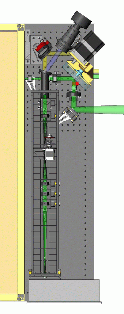
In the picture at left you can see most of the optical layout as well as both the outgoing and incoming light paths. Our Nd:YAG laser produces very short pulses (~95 ps FWHM) of green light (532 nm) at a repetition rate of 20 Hz. The paths of these pulses of laser light are represented as beams in our drawings.
The first two lenses that meet the outgoing laser light (green beam exiting box on left), expand the beam before it hits the reflective patch on our rotating optic. After reflection, the beam passes through a lens ("f/10 lens") which is positioned such that the outgoing beam is expanded to fill the primary mirror. The light exits the telescope as a collimated 3.5 m diameter laser pulse.
The light returning from the moon caught by the telescope is directed to our optical system, seen as incoming light from the right of the picture. It is collimated by our f/10 lens and passed through the rotating optic, which has by this time rotated the reflecting patch out of the way. In the picture the rotating optic's base is goldish in color. The motor is held above the optic and drives the optic via a pulley. This light that passes through this optic is represented as the yellow beam in the picture. It is steered toward the receiver unit (long rectangular box with slots) which will isolate the 532 nm laser light from the rest of the moonlight. The purpose of the receiver is to filter out our reflected laser signal (a few photons per pulse) from all the light from the moon, then focus that signal onto our APD detector array.
The angled snout at the front of the receiver box holds a narrow band filter which passes only green light and reflects all other wavelengths into our CCD camera. By imaging this reflected light we will be able to see where the receiver is looking on the moon's surface, although our actual ability to decipher what we are looking at is determined by the atmospheric seeing. It will be very important to keep stray light out of the receiver in practice, however in this drawing the top has been removed.
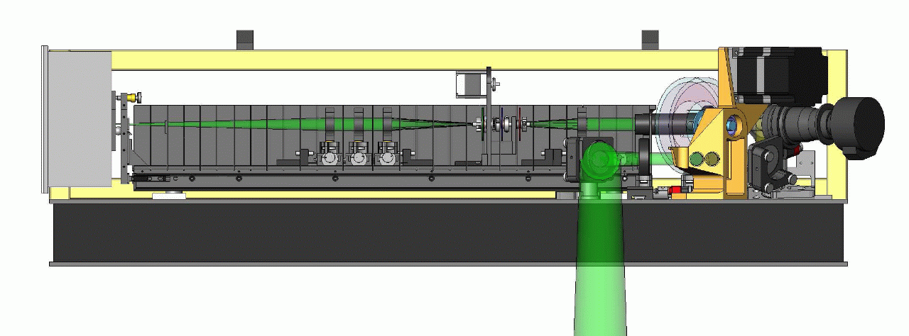
The optics in the receiver will be used to filter out the laser pulses returning from the retro-reflector arrays, from all the other light that has entered the telescope. The slots that run down the length of the box hold baffle plates which have been designed with apertures only slightly larger than that of the beam itself.

Here we see the inner workings of our receiver box. The collimated light entering the enclosure at the right has just passed through a narrow band filter positioned at the front of the receiver snout and consists only of 532 nm light.
From right to left, the first lens in the receiver box is the first component of our spatial filter. This lens focuses the beam into a point at the center of a 400 μm pinhole. The lens following the pinhole then re-collimates the beam. Just before the light reaches the pinhole, it passes through two rotating optics (red and blue disks in picture) which will be adjusted to control the desired attenuation of the beam. Just after the pinhole, the light will hit another rotating optic (green disk) that has a patch of frosted glass on it. This frosted glass will be used to diffuse the telescope's internal corner cube return but it will be rotated out of the way in time for the lunar returns.
The optical mount following the last spatial filter lens is used to hold a masking optic which defines the entrance pupil and central obscuration of our system. The final lens in the receiver focuses the signal down to a focus on our APD lenslet array which is held in our adjustable flexure-mounted APD box positioned at the end of the receiver. The lenslet array distributes the light evenly over our 16 element APD array (not seen in picture).